The Basic Principles Of Spandrel Glass Curtain Wall
Table of ContentsWhat Is Spandrel Glass Fundamentals ExplainedFacts About What Is A Spandrel Glass Panel RevealedThe Spandrel Glass Colors PDFsMore About Spandrel Glass Cost
The masonry design of the non-participating infill is accomplished based on the relevant MSJC Code areas for strengthened or unreinforced stonework(Section 3. 2 for unreinforced infill and Area 3. MSJC Code Section B. 3. 5 helps the developer identify the suitable augmented loads for developing the bounding structure members. Frame participants in bays beside an infill, but not in contact with the infill, should be developed for no less than the forces (shear, minute, and axial)from the comparable strut structure evaluation. The shear as well as moment related to the bounding column needs to be at the very least the results from the comparable strut frame analysis multiplied by an element of 1. 1. The axial loads are not to be much less than the outcomes of that evaluation. Additionally, the horizontal part of the force in the equivalent strut is included in the design shear for the bounding column. 1, as well as the axial loads are not to be less than the outcomes of that evaluation. The upright element of the force in the comparable strut is included to the style shear for the bounding beam or slab. The bounding framework layout need to additionally take right into factor to consider the volumetric modifications in the masonry infill product that might occur in time as a result of regular temperature and wetness variants. 2 m)apart along the border of the infill. Number 2 reveals an example of a mechanical port made up of clip angles bonded down flange of the steel beam of light.
Connectors for both participating as well as non-participating infills are not allowed to move in-plane tons from the bounding frame to the infill. Study(ref. 3 )has shown that when adapters send in-plane lots they create regions of local anxiety as well as can create premature damages to the infill. This damage after that lowers the infill's out-of-plane ability since curving action is prevented. INSTANCE 1: DESIGN OF PARTICIPATINGframe to prevent the unintended transfer of in-plane loads from the frame into the infill. The MSJC Code needs getting involved infills to fully infill the bounding frame as well as have no openingspartial infills or infills with openings might not be thought about as part of the lateral force resisting system because structures with partial infills have usually not carried out well throughout seismic events. 2 )in the late 60s, is the particular tightness parameter for the infill and also supplies a step of the relative tightness of the frame as well as the
infill.
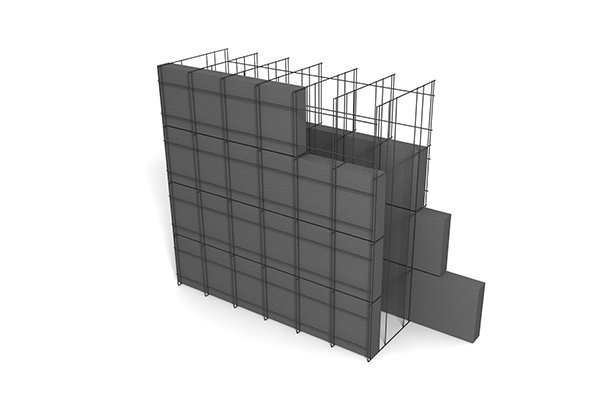
STONEWORK INFILL WALL SURFACE FOR IN-PLANE LOADS Take into consideration the basic framework of Figure 3. Steel frames support all gravity loads and also the side lots in the east-west direction. The bounding columns are W10x45s oriented with the strong axis in the east-west instructions. The bounding beam of lights over the masonry infill are W10x39s. The masonry infill withstands the side load in the north-south direction. Usage small 8-in. =24.
The Main Principles Of What Is A Spandrel Glass Panel
STONEWORK INFILL WALL FOR IN-PLANE LOADS Take into consideration the easy structure of Number 3. Steel frameworks support all gravity tons and the lateral lots in the east-west instructions. The bounding columns are W10x45s oriented with the solid axis in the double glazing panel near me east-west direction. The bounding light beams above the masonry infill are W10x39s. The stonework infill stands up to the lateral load in the north-south instructions - spandrel glass color chart. Usage nominal 8-in. =24.
MASONRY INFILL WALL SURFACE FOR IN-PLANE LOADS Think about the easy structure of Figure 3. Steel frameworks support all gravity loads and also right here the lateral tons in the east-west direction. The bounding columns are W10x45s oriented with the strong axis in the east-west instructions. The bounding beam of lights above the stonework infill are W10x39s. The stonework infill stands up to the side tons in the north-south instructions. Use nominal 8-in. =24.
STONEWORK INFILL WALL SURFACE FOR IN-PLANE PLENTIES Think about the easy structure of Figure 3. Steel frameworks sustain all gravity loads as well as the side load in the east-west direction. The bounding columns are W10x45s oriented with the solid axis in the east-west direction. The bounding beam of lights over the masonry infill are W10x39s. The stonework infill withstands the side load in the north-south direction. Usage nominal 8-in. =24.
The Facts About Spandrel Black Glass Revealed
STONEWORK INFILL WALL FOR IN-PLANE LOADS Think about the basic framework of Figure 3. Steel frames support all gravity lots and the side lots in the east-west instructions. The bounding columns are W10x45s oriented with the strong axis in the east-west direction. Continue The bounding light beams over the masonry infill are W10x39s. The stonework infill resists the side lots in the north-south instructions. Usage nominal 8-in. =24.
MASONRY INFILL WALL SURFACE FOR IN-PLANE LOADS Consider the basic structure of Figure 3. Steel frames sustain all gravity tons and the lateral lots in the east-west direction. The bounding columns are W10x45s oriented with the solid axis in the east-west direction. The bounding beams over the stonework infill are W10x39s (spandrel glass colors). The masonry infill stands up to the lateral load in the north-south instructions. Use nominal 8-in. =24.
Things about Spandrel Glass Curtain Wall
STONEWORK INFILL WALL SURFACE FOR IN-PLANE LOADS Take into consideration the simple framework of Figure 3. Steel structures sustain all gravity lots as well as the lateral load in the east-west instructions. The bounding columns are W10x45s oriented with the solid axis in the east-west instructions. The bounding light beams over the stonework infill are W10x39s. The stonework infill stands up to the lateral load in the north-south direction. Use nominal 8-in. =24.
STONEWORK INFILL WALL FOR IN-PLANE PLENTIES Consider the simple structure of Number 3. Steel frames support all gravity loads and the side lots in the east-west instructions. The bounding columns are W10x45s oriented with the strong axis in the east-west instructions. The bounding beam of lights above the masonry infill are W10x39s. The stonework infill withstands the side tons in the north-south instructions. Usage small 8-in. =24.